I have an Epson V550 perfection for scanning film which is barely adequate. It's just not sharp, it's noisy (sensor-wise), and it doesn't offer me the control I want. I thought it would be fun to measure its modulation transfer function (MTF) and point spread function (PSF) to determine just how soft it is. If you're unfamiliar with what those are and how they're related, LenRentals has a great explanation with real world lens examples. If you find that interesting, I highly recommend checking out the rest of their blog too.
As mentioned in the LensRentals blog post, the MTF is just the Fourier transform of the PSF. I'll be measuring the PSF and using it to calculate the MTF. You can also use the PSF to model what image the scanner would produce, given a known, ideal input:
OUTPUT(x) = INPUT(x) ∗ PSF(x)Convolving your input with the PSF gives you your output. If we know the input and output we can calculate the PSF.
Note: ∗ is convolution
Ideally, the input would be a perfect point source which is expressed as the dirac delta function δ(x). Convolving a function with δ(x) yields the same function (i.e. δ(x) ∗ f(x) = f(x)), so if INPUT(x) is a perfect point source δ(x) then the output would be the PSF. Unfortunately, real world ideal point sources are hard to come by. I could use a pinhole, but I'd need a way of measuring it's diameter which is also hard.
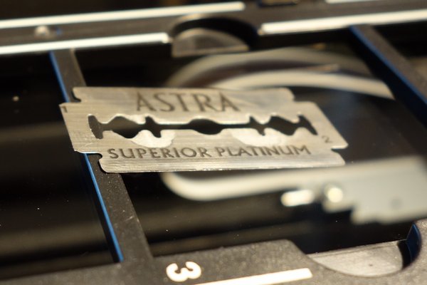
Instead I'll measure the PSF in one dimension at a time. I still don't have an ideal one dimensional point source, but you can get an ideal step function: a razorblade edge. The step function also has a handy property: it's derivative is δ(x). Combining that knowledge with the derivative of two convolved functions we can derive the PSF from just the scanned image of a razorblade edge:
OUTPUT(x) = STEP(x) ∗ PSF(x)Remember: this is only in one dimension; I'll be taking an individual column or row of an image and treating the data in that column/row as samples of the one dimensional OUTPUT(x) function.
Take the derivative of both sides
OUTPUT ' (x) = (STEP(x) ∗ PSF(x)) '
Use the derivative of convolved functions to simplify the right hand side
OUTPUT ' (x) = STEP ' (x) ∗ PSF(x)
Replace STEP'(x) with its derivative, δ(x)
OUTPUT ' (x) = δ(x) ∗ PSF(x)
Convolving a function with δ(x) is the identify transform
OUTPUT ' (x) = PSF(x)
So overall the procedure looks like this:
The razor blade would not fit in the Epson film holders, so I used a slide frame. There is a slight difference in the height (1.0mm for the Epson, 0.9mm for the frame) but that turns out to not make much difference. More on that later.
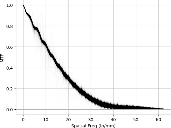
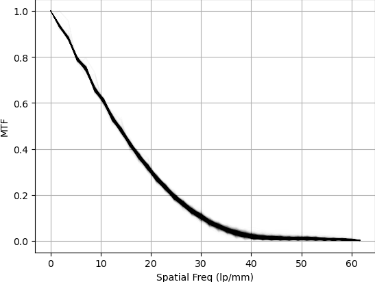
The graph is fuzzy because I plotted the MTF for all rows of pixels crossing over the razor blade edge on the same graph. Any dust, noise, or nicks in the razor blade can cause fuzziness.
 Looking at the two graphs, the scanner is sharper measuring a vertical edge. This means scans of
landscape photos will be sharper vertically than horizontally. In practice, I don't notice this in
actual scans of film, but if you were scanning film shot with an anamorphic lens, it might be a good
idea to mount them in slide frames and rotate them. I wonder if this is in part due to the sensor
bar moving and vibration causing blurriness.
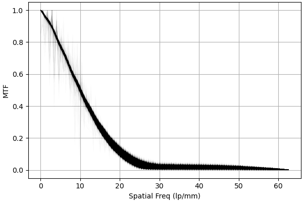
Looking at the two graphs, the scanner is sharper measuring a vertical edge. This means scans of
landscape photos will be sharper vertically than horizontally. In practice, I don't notice this in
actual scans of film, but if you were scanning film shot with an anamorphic lens, it might be a good
idea to mount them in slide frames and rotate them. I wonder if this is in part due to the sensor
bar moving and vibration causing blurriness.
ScanDig has also performed resolution tests on the V600 (which is nearly identical to the V550). They also found the resolution to be different in the vertical and horizontal directions at about 25 lp/mm and 35 lp/mm (to convert from their PPI to lp/mm divide by 50.8). Their test methodology is different from mine. Instead of measuring the full MTF they determine the resolution they can no longer discern the difference between black and white bars in a test target.
Their measurements correspond to an MTF of ~5% on both of my graphs. This seems reasonable as a threshold for the smallest discernible contrast. Since they are not measuring a full MTF curve and rely on human judgement to determine the resolution, our results are not directly comparable, but they are in the same ballpark.
People commonly claim that the V550 film holders do not place the film at the proper height and that custom film holders can solve this problem. I put the razor blade in at an angle, resting on the edge of the slide holder so the height of the edge varied over distance. This allows me to see how the MTF changes with film height.
Then I graphed the MTF at three spatial resolutions (10, 20 and 30 lp/mm) vs the y coordinate the 1d slice of data came from. The noise on the right side of the graph is from where the blade was resting on the edge of the slide holder (4.2mm tall). I kept it in because it let me confirm which end of the graph was (nearly) against the glass (left) and which was significantly above it (right).
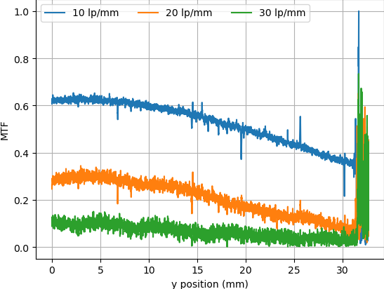
Height above the glass clearly has an effect on MTF, but the best position is about the same as the height the razor blade sits at in the slide holder. I don't think there's much to be gained by buying custom holders unless your film is curling/bowing up significantly. Then again, this could vary unit to unit.
Update 12/21: This subsection was added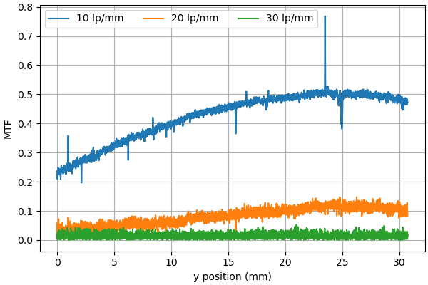
Testing with the razorblade running horizontally at a slant produced similar results; the area of best focus near but not on the glass. The MTF was lower across the board which also matches the MTF curve above where the horizontal edge is not as sharp as the vertical edge.
In a word: No.
VueScan offers the option to auto focus while the SANE API (Linux scanning API) does not report capability. I wondered if it actually does anything. Initially I was thrown off because VueScan was applying curves to the image. When doing MTF tests it's important to not do any nonlinear processing on the image which includes applying curves. I didn't realize this at first and the curves ended up increasing the MTF a bit. This led me down a wild goose chase with me eventually confirming that the autofocus button does not change the commands sent to the scanner in any way. I'll write a follow up to this post with the details later. After spending a couple days doing that I stumbled on the "save raw" button and confirmed that the raw scans from VueScan are in fact no sharper than using the SANE API.
There are several things I still want to investigate: