Since I configure the ADC and DAC to use the same clock, I also don't need to worry about clock drift either.
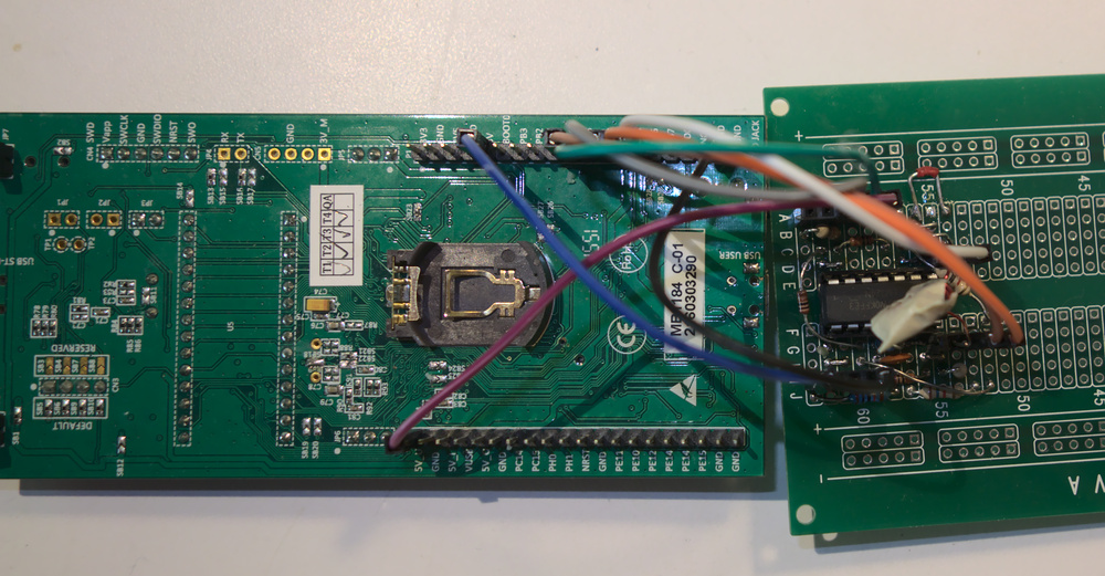
As part of another project, I needed to make my own inductors in the 100-1000uH range. I wrote a python script to control my oscilloscope and function generator to measure them, but I ultimately wanted something standalone where I could just plug in an inductor. I had my STM32L476G-Discovery development board left over from a class in college so I decided to use that.
The project is pretty simple in theory: apply a sine wave to a resistor and the inductor under test in series then measure the total voltage across both and the voltage across just the inductor.
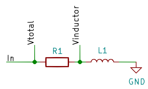
The impedance of the inductor can then be determined by the ratio of voltages.
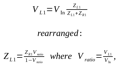
The impedance of an ideal inductor is proportional to the inductance and frequency. Plotting the angular frequency vs impedance gives the inductance as its slope. By measuring impedance at multiple frequencies and using the slope, I minimize the impact of any stray signals that may be present at only one frequency. I can think of three possible sources of interference:
In theory I should be able to determine the ESR (equivalent series resistance) of the inductor from the y intercept of the graph, however this proved impractical. The parasitic capacitance of the inductor causes the graph to bend slightly upward which artificially increases the slope and pushes the y intercept below 0. This does not have a significant impact on the inductance measurement, but does render the y intercept useless.
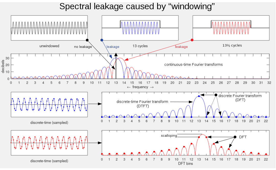
In order to accurately measure the amplitude of the sine waves, as well as to reduce noise, I use a discrete Fourier transform at the frequency of the applied sine wave.

Using the DFT has a few advantages:
Aliasing is another potential problem, which I have ignored entirely. Frequencies above 666kHz will alias. In the future I may add antialiasing filters. See the improvements section below. In practice however, aliasing does not appear to be a significant source of error.
The implementation is pretty straightforward: generate a sine wave at a bunch of different frequencies, measure the impedance at each frequency, then use linear regression to find the slope, which will be the inductance.
There are two tricky parts:
The sine wave generation is mostly straightforward. The DAC uses DMA to load each sample from a sine lookup table. A timer triggers each load every 15 clock cycles (f=1.333Msps).
The tricky part is changing frequencies. To change frequency, the length of the DMA buffer must be changed to represent the new period and the data in the buffer must be changed to reflect that of the new sine wave. However, you cannot change the buffer length while the DMA channel is active. You must change it between samples. The new data also needs to be copied in to the buffer, but only after the DMA has already read the data being overwritten.
Luckily, there are two status flags in the DMA interrupt status register that indicate when the
transfer is half done (HTIFx) and when it is completely done(TCIFx). When
it is half complete I can copy the first half of the new data in. After it is 100% complete I can
change the length (between the last sample and the first sample) and copy the second half.
Normally interrupts would be great for this. However, the interrupt latency is 12 cycles on a cortex-m4. Since changing the DMA buffer length needs to be done in under 15 cycles, doing it in the interrupt would only leave 3 cycles to change it.
Instead of using interrupts, I poll the status bits. I use inline assembly so I can load all of
the constants I need into registers before starting the polling loop, ensuring it switches the
length as quickly as possible once the bit gets flipped. See src/dac.c for the
details.
__asm volatile(
        // wait for the DAC to read the last element
        "loop%=:\n" // wait for the TC flag
        "       ldr     r0, [%[rTCIF]]\n"
        "       cmp     r0, #1\n"
        "       bne     loop%=\n"
        // turn off DMA, Use %[DMAen] as a 0 since only the LSB matter when bit-banding
        // and since all BB'd addressed are word aligned it's always 0;
        "       str     %[rDMAen], [%[rDMAen]]\n"
        "       str     %[rLen], [%[rDMAlen]]\n"
        "       str     r0, [%[rDMAen]]\n"
                : // no outputs, so the volatile keyword is redundant
                : [rTCIF]"l"(&BB(DMA2->ISR)[DMA_ISR_TCIF5_Pos]), // tcif5 flag bit
                        [rDMAen]"l"(&BB(DMA2_Channel5->CCR)[DMA_CCR_EN_Pos]), // dma en bit
                        [rLen] "l" (sine->len), // new len to load
                        [rDMAlen] "l" (&DMA2_Channel5->CNDTR) // address to but new len in
                : "cc", "r0"
        );
Calculating the DFT at one frequency is just the sum of products of the data and cosine (for the real part) or -sine (for the imaginary part). These are stored in static variables and updated by the ISR that fires after the ADC collects half a buffer of data.
I originally had terrible performance until I realized that since the sums were markedvolatile (due to the ISR modifing them), the code in the IRQ handler itself was writing
the sum back to memory every time it modified them instead of keeping them in registers. This is
especially painful since the sums are int64_t and reading or writing them to memory
needs to load or store both registers.
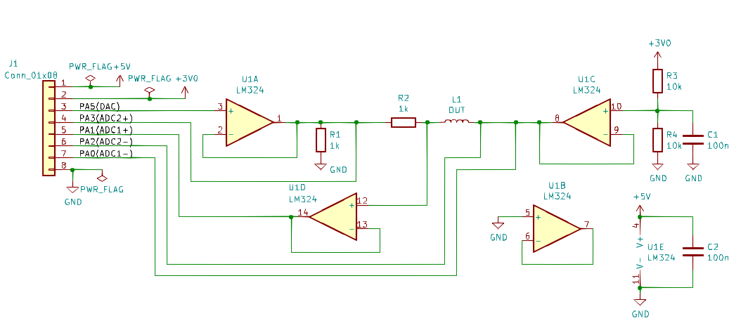
The electronics are simple. Op amps buffer the DAC output and the ADC inputs. One of the op amps
is used as a virtual ground. I used an LM324 op amp because it's what I had on hand,
but it's really a poor choice. It is prone to crossover distortion and has an abysmal slew
rate of 0.5V/us. I added resistors from the op amp output to ground to fix the crossover distortion,
but there's nothing to be done about the slew rate. Finally, its output can't get closer than ~0.5V
from ground when sourcing a few milliamps of current. A much better op amp choice would be a
MCP6294.
I'm pretty pleased with the results. Readings are consistent both with itself and with the original oscilloscope and function generator based version. I can get ~2uH of resolution when measuring a 1080uH inductor, which is pretty good.
I was hoping to also calculate the ESR of the inductor by using the y intercept of the frequency vs impedance graph. Unfortunately the parasitic capacitance causes a slight bend upward in the graph which while not effecting the slope in a major way, does push the y intercept negative, which indicates the measurement is nonsensical.
The biggest improvement would be adding gain to the op amp measuring the voltage across the inductor. Currently the voltage is quite low, even with a large (1080uH) inductor and most of the ADC resolution is wasted. A digipot could be used to set the gain, though increasing the gain would certainly call for a better op amp.
I'd also like to run the ADC at a faster sample rate, which would require the DFT calculation to
be faster. The Cortex-M4 has instructions as part of the DSP extension that would work well:
SMLAL{TT,TB,BT,BB}. These would allow me to load both sine and cosine values packed as
two 16 bit halfwords in a word and directly multiply them with the packed halfwords from the ADC.
Unfortunately, GCC 10.x has a regression that prevents them from being generated. I've bisected GCC
and found the commit it was introduced in. I'm currently trying to see if I can fix it and submit a
patch upstream.
Adding antialiasing filters would reduce the chance of unwanted signals aliasing to a frequency being measured. Since I'm sampling at a much higher frequency than the signal, a simple RC filter would probably be more than adequate. Additionally, adding a low pass filter to the DAC output could eliminate the stairstep effect.